Landing Performance
1 GENERAL
Landing performance tool calculates landing performance parameters based on the aircraft manufacturer’s performance algorithms (Manufacturer-provided SCAP modules), operator-specified policies, and applicable regulations. Advanced optimization techniques are used to maximize performance.
The system designed to minimize the occurrence and effects of flight crew error and maximizes the identification and resolution of errors. If user-entered data is not of the correct format or type needed by the application, the EFB do not accept the data. An error message provided that communicates which entry is suspect and specifies what type of data is expected. The EFB system incorporates input error checking that detects input errors at the earliest possible point during entry.
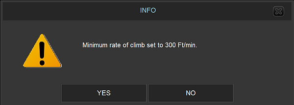
Color-coding philosophies and symbols are used for EFB applications. “Red” color used only to indicate a warning level condition.
“Amber” color used to indicate a caution level condition.
2 BENEFITS
The benefits of landing performance tools,
-
Reduce paper in the cockpit, therefore saving weight and reducing clutter,
-
Reduce cost and workload required to update documents,
-
Keep information up to date, enabling easy document revision,
-
Reduce fuel cost through accurate take-off, landing and weight and balance calculations,
-
Improve safety with onboard performance calculations,
-
Increase payload with real-time performance calculations,
-
Reduce pilot workload
3 REGULATIONS
In normal operations, limitations are not very constraining and, most of the time authorize dispatch at the maximum structural landing weight. This leads to a minimization of the importance of landing checks during dispatch.
However, landing performance can be drastically penalized in case of;
-
inoperative items,
-
adverse external conditions, or
-
contaminated runways
4 OBJECTIVES
Strongpilot landing performance module was developed to fulfill these basic objectives:
-
User friendly standardized module that is same for all aircraft types,
-
Check the consistency and validity of the pilot‘s input and constrain it,
-
Input runway shortening, (Begin/End of runway/Width),
-
Cover customized MEL/CDL items, that effects landing performance and check the user‘s input of MEL/CDL,
-
Compute and display,
-
Maximum Limiting Weight,
-
RLD (Required landing Distance),
-
Brake Cooling time (Boeing A/C only),
-
Autobrake landing distances,
-
Approach climb gradient,
-
Landing climb gradient,
-
VREF/VLS/VApp speeds,
-
Go-Around N1,
-
Approach Climb Speed,
-
Minimum control speed,
-
Limiting factors,
-
One engine-out special procedure (EOSID),
-
Dispatch Release,
-
Inflight Failure calculation,
-
Non-Normal Calculation.
-
ECAM Connectivity (for A350)
5 SUPPORTED AIRCRAFT TYPES
EFB package supports EASA AMC-20-25 / FAA AC120-76 requirements. All data updated via local and/or internet from the server automatically. EFB is based on an open-systems design and provides an integrated operating environment for data sharing hosted EFB applications.
6 LANDING PERFORMANCE BASIS
6.1 CALCULATION STRUCTURE
Based on the SCAP (Standard Computerized Airplane Performance) requirements; Strongpilot Takeoff and Landing performance are based on aircraft manufacturer software and databases according to the SCAP standard. Strongpilot will provide both applications on the condition that customer supplies Strongpilot with the aircraft manufacturer software modules and databases, ensuring that all input and output parameters at the modules’ interfaces are handled according to the SCAP standard.
Only these values, supported by the respective SCAP interface, will be displayed by Strongpilot Takeoff and Landing.
Following schematic shows the performance calculation structure.
Not: Airport obstacle database provided by customers.
6.2 CALCULATION METHODS
All performance calculations based on manufacturer SCAP databases except;
-
Some MEL/CDL weight reductions which is not covered in SCAP databases,
-
INFO, CAUTION, WARNING messages.
6.3 PERFORMANCE DATABASES
SLM (Strongpilot Landing Performance module) uses following databases for calculation.
-
Manufacturer aircraft SCAP database (prepared and maintained by aircraft manufacturer)
-
Airport (Obstacle) database (prepared and maintained by customer)
-
Aircraft registration database (prepared and maintained by software provider)
-
Company aircraft database (prepared and maintained by software provider)
-
Configuration file database (prepared and maintained by software provider)
-
CDL database (Airbus only)
-
MEL / CDL setup database (prepared and maintained by software provider)
6.4 USER PREFERENCES
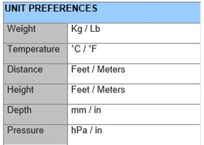
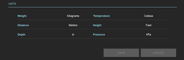
Allows predetermine of the defaults for program execution, such as weight and temperature units, distance units, etc.
Choose your unit preferences using the buttons for each of the selections.
Default setup of preferences are shown in the following picture.
6.5 TRACKED DATA LOGS
Landing performance calculation results are kept in memory for further research or investigate. These tracked data are sent to the dedicated server automatically when internet connection is available.
Pilot may decide the which calculation is the final for real flight.
6.6 MEL/CDL ITEMS
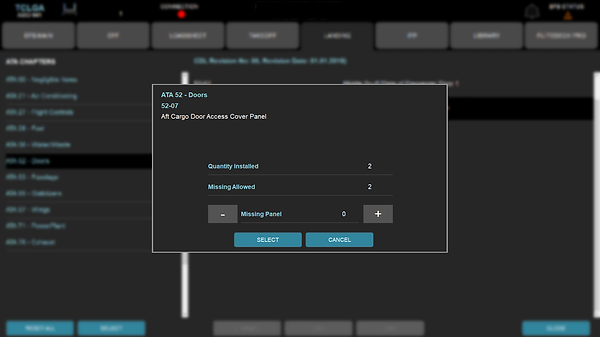
Performance tool uses a database to maintain all the performance-related Minimum Equipment List (MEL) and Configuration Deviation List (CDL) penalties.
Please note that only those MEL or CDL items are shown which affect the performance calculation. MEL or CDL items which do not influence the performance calculations are not listed.
One simply clicks on the MEL or CDL button on performance tool displays the MEL/CDL selection screen.
Following illustration shows CDL 52-07 box clicked in the CDL screen for selection.
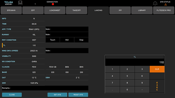
6.7 ATIS ENTRY
Required inputs for performance module like runway direction, runway condition, wind direction & speed, OAT and QNH may be entered directly from main performance GUI.
In addition, ATIS form is designed to keep and set all ATIS information to performance tool via separate window. When recorded, data(s) may be set to landing performance tool by pushing SET ATIS button from ATIS form.
6.8 INFO / NOTAM
Software has the capability to introduce NOTAM' s and/ or shortening into the landing calculation. This added Notam does not store in the database.
The information on this screen is defined by the following:
BR
The distance that the runway is to be shortened from the start of the landing roll in the units specified at the right side of value.
EOR
The distance that is to be taken from the liftoff end of the runway in the units specified at the right side of value.
Width
The distance that is to be taken from the width of the runway in the units specified at the right side of value.
6.9 DATABASE INFO
All database versions and some of the Aircraft limits which are used in calculation is listed in DB INFO page.